Advent of Code 2024 Day 24 Part 2 Explained - Crossed Wires
You can find my Rust implementation on Github.
Part 1 - Simulating the Logical Gates
Basically, we have boolean logical gates (XOR, AND, OR)
- Taking 2 boolean as input.
- Producing one boolean as output.
Inputs and outputs are labelled (x01, njn, z12, ..). Each gate define the labels of his inputs and output.
The puzzle input gives the values for some labels. But for some gates, we don't have the input values yet - we need to compute some gates first to get these values.
After simulating all the gates, we end up with a bunch of values starting with the letter z (z00, z01, ..).
Combining these bits produce a number, which is the answer for part 1.
I'm not gonna dig much into part 1 because it's simple and doesn't really help for part 2, which is the interesting part.
Part 2 - Debugging the Logic Circuit
The gates actually represents a logical circuit which tries to sum 2 numbers. The values in puzzle input are the binary representation of 2 numbers:
- X =
... x02 x01 x00 - Y =
... y02 y01 y00
And the output of the circuit is Z = ... z02 z01 z00.
If the circuit was working properly, we should have X + Y = Z.
The gates of the circuit are connected together by wires which takes the output of a gate and plug it as input for another gate. But there have been 4 wires swaps, so the circuit is not working as expected. The goal is to find these 8 wires (2 by swap), and swap them back to make the adder works again.
Printing the Binary Values
I didn't know where to start.
So I printed:
- The expected Z value, in binary.
- The Z value produced by the circuit, in binary.
Expected = 1000011000101111111110101011110010010001110000
Produced = 1000011001000000000000101011101110000001110000
z00 being the rightmost bit here
It doesn't help in any way to solve the problem, but at least we can observe it. Yay!
At least, we can notice that the first difference appears at z10. Which means the beginning of the circuit is working fine, until z10.
So there is probably wires to swap around z10.
But still had no idea which wires to swap.
My Brain Wasn't Working, But My Eyes Were
When my brain can't find a solution, I try to visualize the problem - I'm someone who need to see the things.
The circuit is just inputs and outputs (xXX, yXX, zXX), gates, and wires connecting everything. So a graph.
I usually use a pen and some paper, but the graph looked big. So I decided to use Graphviz instead. I wrote a script in Rust that takes the datastructure I used for part 1, and build a .dot file representing the logical circuit of the puzzle input as a graph.
You can see the result here.
Good idea to use Graphviz, it would have taken me a lot of paper and time to draw it.
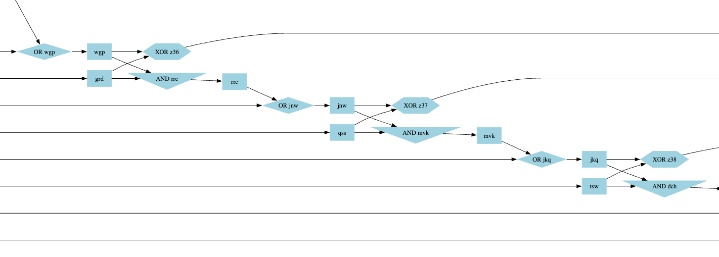
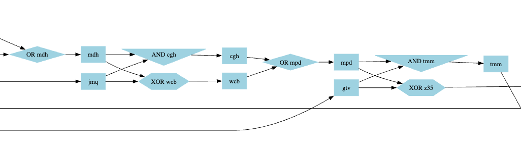
And the result relieved me. It looks like there are patterns, which is expected for a sum as it's just summing at the current index, then moving to the next with the carry. This means 4 patterns should look different.
The first bit that differs in the output is z10, so I've looked around it on the graph.
The pattern that seems to work is the following:
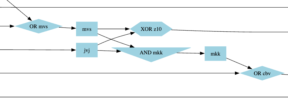
For z10, we have:
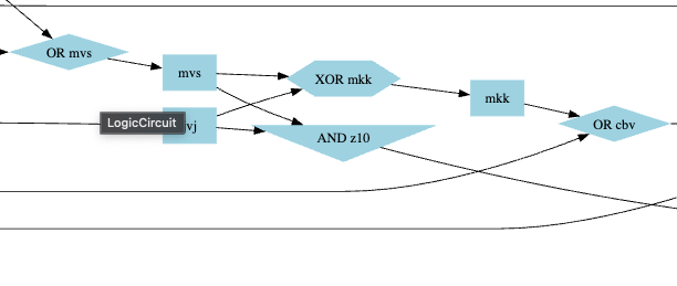
Swapping the wires mkk and z10 in the puzzle input fixed it:
I found 2 similar broken patterns, which I fixed by doing the necessary swaps.
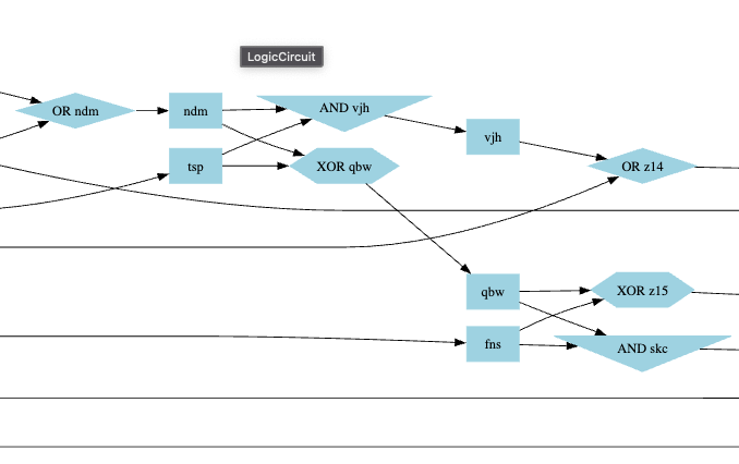
3 swaps on 4, and no similar pattern left to fix. So I ran again the code that compares the expected output and produced output. There was still a difference on bit 25.
Each xXX yXX pair goes though a XOR gate and a AND gate. For x25 and y25, 2 wires needed to be swap:
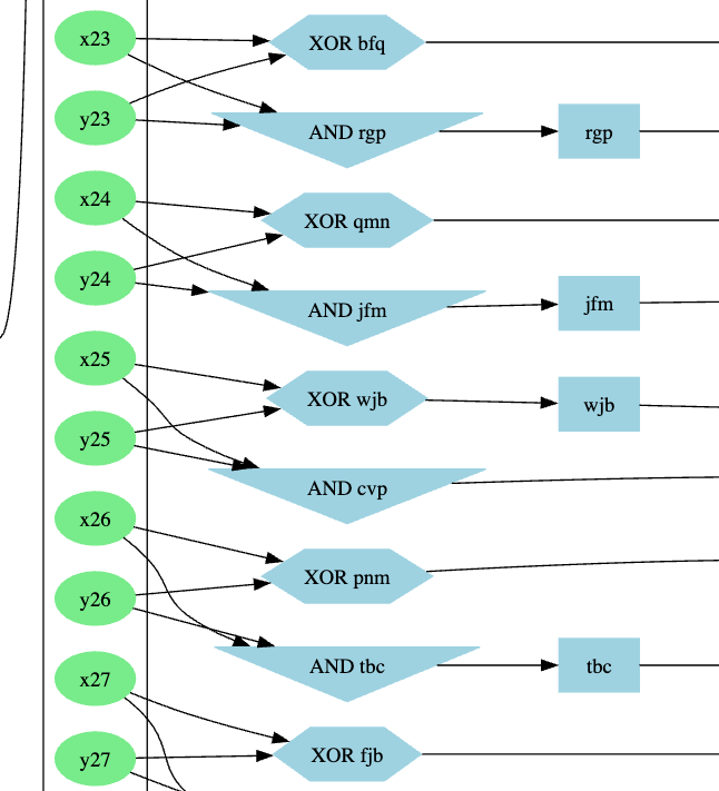
And that's it. The circuit is now working as expected:
Expected = 1000011000101111111110101011110010010001110000
Produced = 1000011000101111111110101011110010010001110000
See the fixed graph here.